|
|
|
|
|
2013
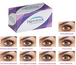
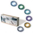
Эти линзы специально разработаны для людей с темными глазами. Трехтоновые цветные линзы легко перекр...
Подробнее »2013
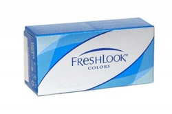
Эти линзы придадут вашим глазам удивительные оттенки. Они сделают Ваш взгляд очаровательным и нежным...
Подробнее »2013
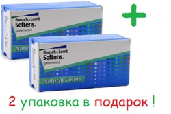
Акция Купив одну упаковку цветных контактных линз Soflens Natural Colors, вы получаете вторую упако...
Подробнее »2013

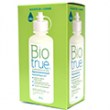
Увлажняющие и смазывающие капли ReNu MultiPlus разработаны компанией Bausch+Lomb для создания допол...
Подробнее »2013
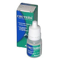
Благодаря уникальной формуле СИСТЕЙН ® сразу после закапывания быстро снимает покраснение глаз, сух...
Подробнее »2013
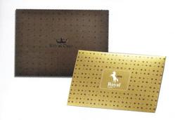
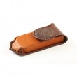
Салфетка из микрофазы с силиконовыми узорами (обратная сторона оригинально обработана силиконом не ...
Подробнее »2013
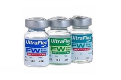
Оттеночные линзы Ultra Flex Next прекрасно подходят для светлых глаз. Эти линзы изготовлены по специ...
Подробнее »2013
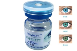
Оттеночные линзы OKVision - INFINITY прочные тонкие линзы, идеально подходят при высокой степени дал...
Подробнее »

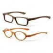
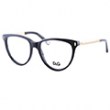
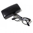
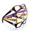
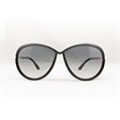
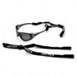
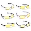
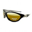
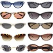


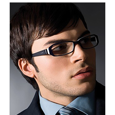
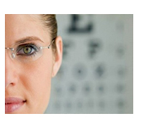
 Сегодня очки носят не только люди, страдающие от плохого зрения, но и те, кто считает оправы модным аксессуаром.